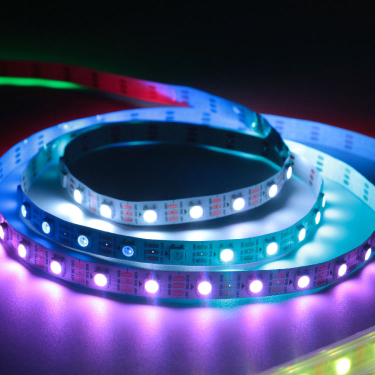
A pixel LED strip installation succeeds or fails before the first strip is mounted. The installer must align the strip voltage, IC protocol, pixel map, controller capacity, power distribution, mounting method, and environmental protection. Missing one of those decisions can cause flicker, wrong colors, dim sections, overheated connectors, or a system that is difficult to service.
This guide follows the order used in a real lighting project: confirm the design, calculate the electrical load, prepare and test the hardware, install it, and commission the finished system.
What Must Be Confirmed Before a Pixel LED Strip Installation Starts?
Which strip voltage, protocol, and color format does the project require?
Start with the effect, viewing distance, and required pixel resolution. Then confirm the operating voltage, IC protocol, RGB or RGBW format, pixels per meter, cut unit, color order, and controller output limit. Connector shape is not proof of compatibility.
For example, the High Brightness GS8208 Flexible Strip Light RGB DC12V SMD5050 Customized Addressable LED Strips uses DC12V and a GS8208 IC; model SJ-10060-8208-12V is a 60-pixel-per-meter option with dual data paths. The Outdoor Programmable Flexible Strip Light RGB DC5V SK6812 Addressable LED Strip is a DC5V RGBW family offered in several pixel densities. These products require different power and controller settings even though both are pixel strips.
How should runs and controller outputs be divided?
Give every run a unique ID. On the drawing, record its length, pixel count, data direction, controller port, power branch, injection points, cable route, and nearest service joint. Keep important connectors and controllers accessible; burying a joint behind a finished wall turns a minor repair into demolition.
For early specification work, our LED strip light range helps project teams compare addressable formats before finalizing the controller map and bill of materials.
How Do You Calculate Power Capacity and Power-Injection Points?
How is the power of a pixel LED strip calculated?
Use the exact product data rather than a generic watts-per-meter assumption:
Total power (W) = strip length (m) × rated power (W/m)
Current (A) = total power (W) ÷ operating voltage (V)
Consider a 10 m run of the 12V GS8208 strip at 60 pixels/m and 12W/m. The load is 10 × 12 = 120W, or 120 ÷ 12 = 10A. If it is divided into two 5 m power branches, each branch carries a calculated 60W or 5A. Select the supply according to its continuous-load rating, temperature derating, ventilation, and the manufacturer’s required operating margin. Do not treat a software brightness limit as the only protection for undersized wiring.
Where should power be injected?
There is no universal injection interval. It depends on voltage, current, conductor size, strip copper, brightness, cable length, and allowable voltage drop. Plan candidate injection points at branch starts, ends, or intermediate positions, then measure the voltage at the remote pixels while a demanding scene is running. Add or reposition feeds if the measured voltage, color, or brightness is inconsistent.
Size every cable, connector, terminal, and fuse for its branch current. The controller and strip need the correct ground reference for data. If multiple power supplies are used, follow the equipment manufacturer’s topology; do not join their positive outputs unless the system is specifically designed for parallel operation. Fixed mains wiring should be completed by qualified personnel under applicable electrical rules.
What Tools and Components Are Needed Before Installation?
Which components and tools should be ready?
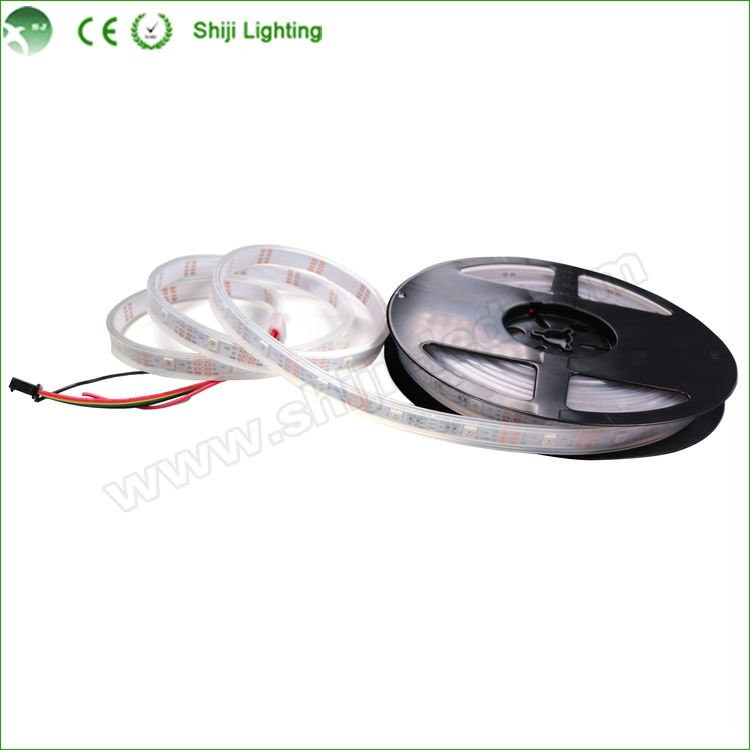
Prepare the compatible controller, regulated DC supply, correctly sized power and signal cables, branch protection, connectors, enclosures, and any required level shifter, signal conditioner, or differential transmitter. Installation tools normally include a multimeter, wire cutters, stripper, crimper or soldering equipment, heat-shrink, labels, profile or clips, strain relief, sealant, end caps, and surface-cleaning materials.
Adhesive backing alone is rarely enough for overhead, warm, dusty, humid, or outdoor locations. Use a suitable aluminum profile or mechanical clips. For weather-exposed work, the strip’s IP rating does not protect an unsealed cut end, connector, cable entry, controller, or power supply.
What must be tested before going to the site?
Bench-test every reel and controller output. Display red, green, blue, white, and a moving pattern. Confirm voltage, IC selection, pixel count, color order, data direction, and port mapping. Label each tested section before packing it. This catches incompatible settings and damaged pixels while every connection remains easy to reach.
How Do You Install and Wire a Pixel LED Strip Correctly?
How should the strip be mounted and connected?
Clean and dry the mounting surface. Cut only on marked lines, and never fold the flexible PCB across an LED or solder joint. Follow the specified bend radius and support cable weight, and keep the strip flat in its profile. Reseal every opened waterproof layer and provide drainage where water could collect.
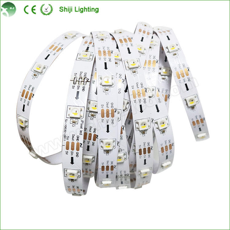
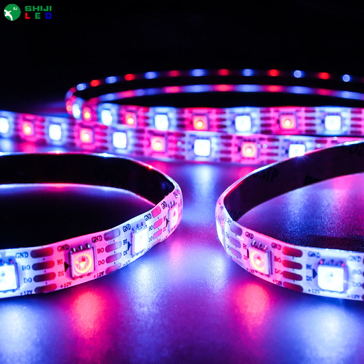
Read the pad labels before wiring. Power pads may be marked V+ and GND; signal pads may show DIN, DOUT, DI, DO, or clock markings. Data enters through DIN and follows the printed arrow. Wire color and connector gender can vary, so neither should replace the PCB labels or product drawing. Power may be distributed to several points even though data has one defined direction.
Which controller settings must be verified?
With the power off, check polarity, data input, ground reference, branch fuses, strain relief, and terminal tightness. Energize one branch at low brightness. Configure the IC type, pixel count, RGB/RGBW order, output mapping, refresh parameters, effect direction, and initial brightness limit. A 3.3V controller driving some 5V strip types may require a suitable level shifter; long signal routes may require differential transmission.
How Do You Test, Troubleshoot, and Hand Over the Finished System?
Which commissioning checks are essential?
Start one power branch at a time. After basic colors work, run the maximum expected scene long enough for temperatures and voltage to stabilize. Measure the supply and remote feed points under load. Touch-safe inspection or appropriate instruments should be used to check the power supply, connectors, cables, and strip for abnormal heating.
Use symptoms to shorten diagnosis:
| Symptom | First checks |
| No output | DC voltage, polarity, DIN, controller port, and IC setting |
| Correct first pixels, dead remainder | First failed pixel, preceding joint, pixel count, and mapping |
| Wrong colors | RGB/RGBW color-order setting and channel map |
| Random flicker | Ground reference, loose joints, signal length, noise, and load voltage |
| Dim or discolored end | Remote voltage, cable loss, branch load, and injection position |
| Controller resets | Supply capacity, distribution wiring, overload protection, and brightness demand |
What should be included at handover?
Record the controller project file, IC setting, pixel count, port map, brightness limit, power-supply and fuse assignments, measured voltages, cable labels, and service-access points. Photograph sealed joints and distribution panels before they are concealed. Keep one approved replacement section from the same production batch when color matching is important. At SHIJILIGHTING, we recommend treating this record as part of the lighting system, not optional paperwork.
FAQ
Q: How do I calculate the power supply size for a pixel LED strip?
A: Multiply the verified watts per meter by the installed length, or multiply the maximum current per pixel by the pixel count. Convert watts to amps using the operating voltage, then apply the power-supply manufacturer’s continuous-load and temperature-derating guidance.
Q: Where should I inject power into a long pixel LED strip?
A: Place feeds where calculations and voltage-under-load measurements show they are required. Typical locations include the start, end, or intermediate branch points, but the final spacing depends on voltage, current, cable size, strip construction, and brightness.
Q: Which end of an addressable LED strip connects to the controller?
A: Connect the controller signal to the end marked DIN, DI, or an arrow pointing into the strip. Do not determine data direction from wire color or connector gender alone.
Q: Can a pixel LED strip be installed outdoors?
A: Yes, when the strip and the complete system suit the environment. The installer must protect cut ends, connectors, cable entries, enclosures, mounting points, and drainage—not only select a strip with an outdoor IP rating.
Q: Why does a pixel LED strip flicker or show random colors?
A: Common causes include an unstable ground reference, excessive signal distance, electrical noise, loose joints, incorrect IC settings, or voltage sag under load. Check supply voltage and connections first, then test the signal path from the first affected pixel backward.