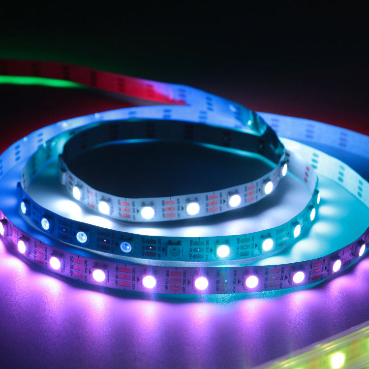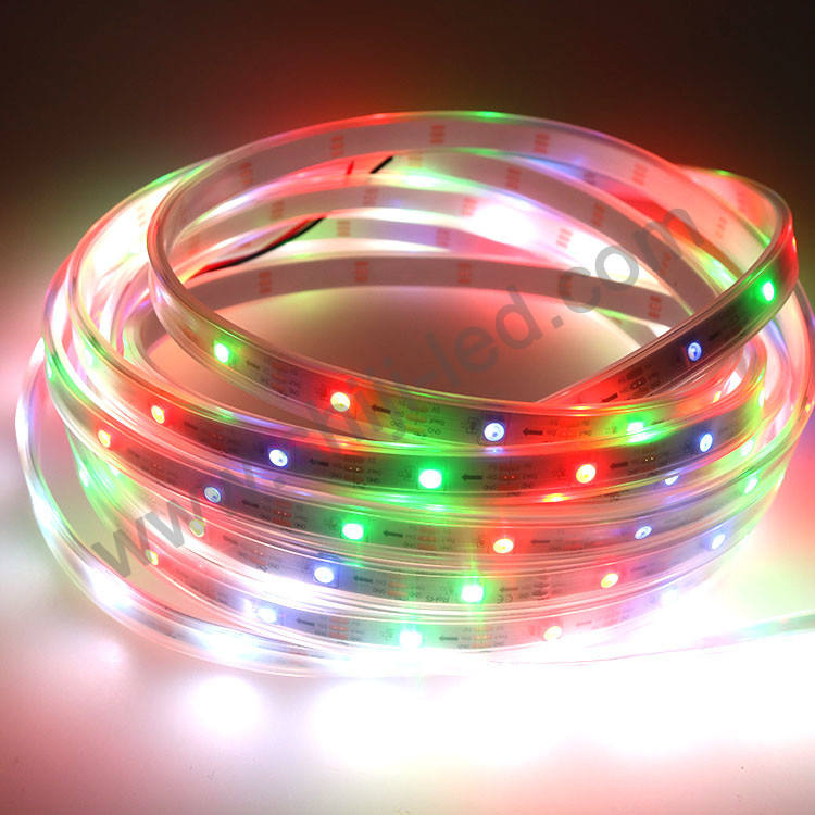
Programmable LED Strips can fail in surprisingly ordinary ways. Colors may change at the far end, pixels may flicker, or the controller may stop responding after mounting. Most of these problems begin before programming. A short preflight check can prevent damaged pixels, repeated soldering, and costly access work.
Start with a Preflight Check, Not a Fault Hunt
Check the system in the same order that electricity and data move through it. Do not hide wiring or seal joints until each gate below passes.
- Compatibility: If nothing lights or colors are wrong, match voltage, IC, channel type, and controller output.
- Power: For dim or discolored pixels at the far end, calculate load and plan power distribution.
- Data: For random flicker or no response, confirm data direction, ground reference, and cable length.
- Physical work: To prevent intermittent sections after mounting, inspect cuts, solder joints, strain relief, and seals.
- Commissioning: If a simple test works but the show fails, test the planned load and save the final settings.
This sequence keeps diagnosis focused. Code will not repair a voltage mismatch, while a system that passes a short bench test but fails at full length usually needs power or signal checks.
Mistake 1: Matching Parts by Connector Shape Alone
Check Voltage, IC Protocol, and Channel Type Before Wiring
JST-style plugs are convenient, but their shape and wire colors are not a compatibility standard. Trace conductors to their labeled pads. Confirm voltage, polarity, IC protocol, and whether the product uses data only or separate data and clock lines.
The Addressable Smart Strip Lights APA102C SK9822 DC 5V 60leds/m LED Strips illustrate the point: this DC5V product uses APA102 or SK9822 control and a four-conductor connection. A controller configured for a one-wire chipset is not interchangeable simply because an adapter can be attached.
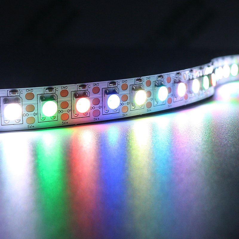
At SHIJILIGHTING, we recommend writing the voltage, chipset, channel type, and pin order on the project wiring sheet before any reel is cut. That small record prevents mixed stock from entering a large installation.
Confirm Controller Output, Logic Level, and Color Order
Verify that the controller supports the chosen IC and pixel count. RGB and RGBW products need different channel settings. An RGBW strip configured as RGB may show shifted colors or lose addressing because the controller sends the wrong number of values.
Logic level matters too. A controller can appear stable on the bench yet flicker after the data cable is extended. Use the controller and strip specifications to decide whether a suitable level shifter is required. The Decorative Lighting Customized Digital LED Strip 5V Flexible RGBW Strip Light is a useful reminder to confirm both the 5V supply requirement and the RGBW channel configuration rather than treating every digital strip as three-channel RGB.
Mistake 2: Sizing Power from Reel Length Alone
Calculate the Planned Maximum Load with Safe Headroom
“Five meters” is not a power specification. Load changes with pixel density, channel count, brightness limit, and the displayed scene. Use the exact model’s rated watts per meter or maximum current, multiply by installed length, and provide suitable headroom.
Do not base the calculation only on a low-brightness animation. A commissioning scene that turns many channels on together can expose an undersized supply immediately. Compare specifications within the LED strip product range because two reels of equal length may have very different voltage and power requirements.
Plan Wire Capacity, Fusing, and Power Injection Before Mounting
The supply may be large enough while its distribution wiring is not. Thin conductors, long runs, small connectors, and PCB traces add resistance. Symptoms include a dim far end, color shift, resets, or warm connectors.
Plan injection points from measured load and acceptable voltage drop, not from a fixed distance copied from another project. Size conductors and protective devices for each branch. When several supplies are used, keep their positive outputs in their intended sections and follow the approved common-reference design. High-current or mains-side work should be reviewed by a qualified electrical professional.
Mistake 3: Treating the Data Line Like a Power Wire
Feed Data into the Correct End and Protect the First Pixel
Power can enter at several points, but pixel data travels in one direction. Feed the pad marked DIN, DI, or an arrow pointing away from the controller. Connecting to DOUT can leave the strip dark even when voltage is present.
Keep the controller-to-first-pixel lead short and route it away from noisy power wiring. Use any data-line protection specified by the controller or strip supplier. Do not assume that the connector fitted to the reel identifies the input end; verify the printed pad markings.
Maintain a Common Reference and Control Long Signal Runs
The data signal needs a reference. Without the required common ground, the first pixel may interpret a clean controller output as noise. Flicker that changes when a cable is touched often indicates a connection problem.
Long gaps between the controller and first pixel also deserve separate design work. A thicker power cable does not repair a deteriorating digital waveform. For extended distances, use a suitable level-shifted or differential signal solution specified for the controller, and keep the return path with the data conductors.
Mistake 4: Cutting, Joining, and Mounting Before a Bench Test
Cut Only at Marked Pads and Build Serviceable Connections
Measure twice, then cut only through the marked copper-pad line. Cutting between pixels can remove the area needed for reconnection or break a controlled group. Avoid flexing the PCB repeatedly beside a solder joint; add strain relief so movement is carried by the cable or mounting hardware.
Test every new section before adhesive, clips, or channels make it difficult to reach. Check continuity with power disconnected, inspect for solder bridges, and confirm polarity and data direction again after each splice.
Restore Weather Protection and Provide Heat Management
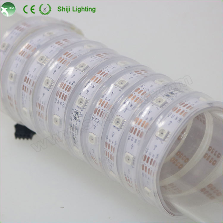
A waterproof reel does not remain waterproof after cutting. Reseal every new end, wire exit, and splice with a method compatible with the jacket and environment. Keep joints out of standing water and add strain relief.
Mounting also affects service life. Use a clean, stable surface and suitable clips or profiles. Avoid sharp bends across components, sealed cavities with trapped heat, and inaccessible joints. Our project support at SHIJILIGHTING considers maintenance access part of the installation, because a replaceable section is far less disruptive than a permanently buried fault.
Mistake 5: Skipping a Staged Commissioning Test
Verify Pixel Count, Chipset, and Color Order with Simple Patterns
Begin with a short, known-good section at limited brightness. Display solid red, green, blue, and white, followed by one slowly moving pixel. These tests reveal swapped color order, an incorrect RGBW setting, the wrong pixel count, or a break in the data path more clearly than a fast rainbow animation.
Add sections one at a time. If the fault appears after a particular joint, investigate that boundary before changing the entire program. Record the working chipset, pin assignment, color order, pixel count, and brightness limit.
Test the Planned Load and Record the Working Configuration
Finish with the longest cable route and the most demanding scene expected in normal operation. Measure voltage at the supply and at distant injection points under load. Watch for color shift, flicker, restarts, hot connectors, or delayed controller response.
Before handover, label power branches, data direction, controller ports, and replaceable sections. Save a copy of the controller configuration and test pattern. This turns future maintenance into a controlled comparison instead of another fault hunt.
FAQ
Q: What is the most common mistake when using Programmable LED Strips?
A: The most damaging mistake is connecting components before confirming voltage, chipset, pin order, and controller compatibility. A matching plug does not prove that the electrical specifications match.
Q: Why do Programmable LED Strips flicker even when the power supply is large enough?
A: Flicker can come from a missing common ground, an unstable data signal, an excessively long data lead, a loose joint, or voltage drop in the distribution wiring. Check those items separately.
Q: How can voltage drop be prevented in long programmable LED strip runs?
A: Calculate the actual load, choose suitable conductor sizes, divide the installation into planned branches, and add power injection where measurements show it is needed. Test voltage under the intended operating scene.
Q: Can Programmable LED Strips be cut anywhere?
A: No. Cut only at the manufacturer’s marked copper-pad locations. Cutting elsewhere can damage a pixel group, remove reconnection pads, or stop data from reaching the following section.
Q: What should be tested before Programmable LED Strips are permanently mounted?
A: Verify voltage, polarity, data direction, chipset, color order, pixel count, every splice, and full-load behavior. Complete these checks before applying adhesive, sealing joints, or closing channels.